
본문
OSI and TCP/IP model (while Modbus is an application layer protocol). There are a number of other things to note with this model. As there is no error during those steps, the server responded function code will also be the function code sent from the client. If there is no error during the execution process, the data field of the ADU response from server to client will include the data requested, i.e. the data the client previously received. If server receives the request and is unable to execute it (e.g client requests to read a non-existent register), RS485 standard server will return an exception response to client to indicate the nature of the error. TXsoil can be configured and read with a smartphone or PC, with just a few clicks. This example reads and processes data from RS485 Isolator clicks. Single-ended lines can quickly corrupt the data they carry when used over very long distances. In RS-232, single-ended lines or unbalanced signaling is used and this lowers the noise immunity of the standard against interferences such as ground loops. In environments where excessive interference and noise still compromises network stability, line biasing (the use of pull-up/pull-down resistors on the differential pair) is required.
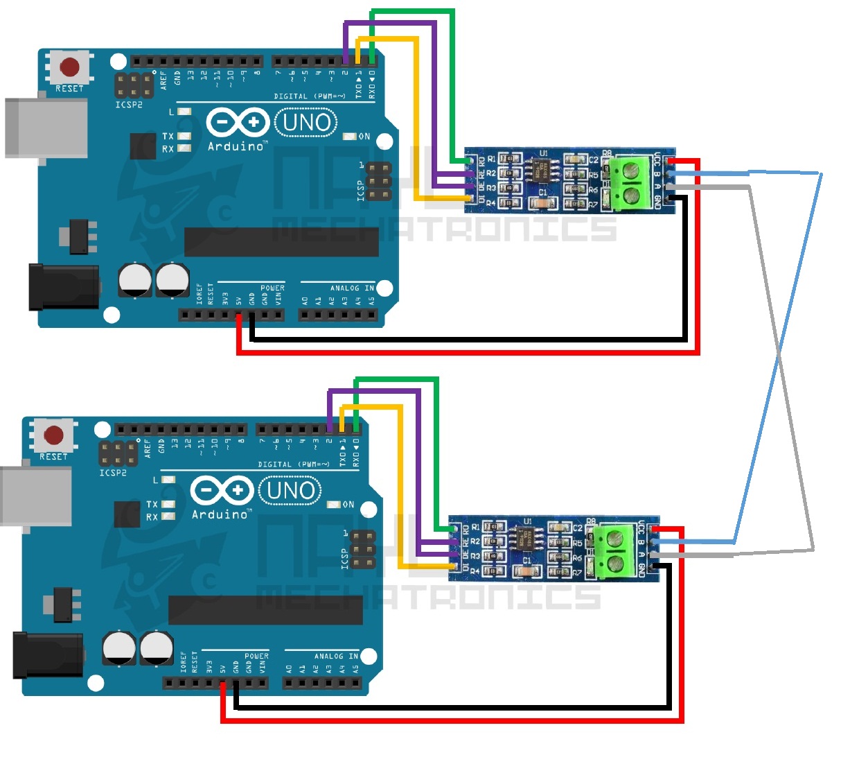
However the bias resistors effect the total termination resistance. With no driver connected, the differential voltage on the wires will depend on the termination resistor and biasing. If server cannot receive the request as having communication channel error, server will not response anything to the client. If server receives the request and detect an error on the communication channel (e.g parity, LRC, CRC), server will not response anything to the client. If you are running asynchronous start/stop communications (a UART) across the RS-485 wires, it simply will not work if the polarity is backwards. These distances can be overcome by running fiber optic cables between the sites and having them connected together via Ethernet gateways. To support Modbus communication on a network, many modems and gateways incorporate proprietary designs (refer to the diagram: Architecture of a network for Modbus communication). ◆ Support level and vertical installation to satisfy users' different requirements. The Modbus Organization is an association of users and suppliers of Modbus-compliant devices that advocates for the continued use of the technology. User-Defined Function Codes are function codes defined by users. Modbus defines three types of function codes: Public, User-Defined and Reserved. Modbus gives two range of values for user-defined function codes: 65 to 72 and 100 to 110. Obviously, user-defined function codes are not unique.
RS-232 is used for connecting only two devices. In other words, each local UART on the wildcard can both send data to and receive data from a remote UART on the other end of a connecting serial cable. Function code 01 (read coils) allow reading the state from 1 to 2000 coil of a remote device. For example, when a MCU connects to a sensor to read its data by Modbus on a wired network, e.g RS485 bus, the MCU in this context is the client and the sensor is the server. For data encoding, Modbus uses a big-endian representation for addresses and data fields. It was developed for industrial applications, is relatively easy to deploy and maintain compared to other standards, and places few restrictions on the format of the data to be transmitted. In fact, other remote temperature measurement devices already exist, but they are usually expensive to maintain: we wanted something that was not only excellent and working with the most used standards, but even undemanding!
Modbus is often used to connect a plant/system supervisory computer with a remote terminal unit (RTU) in supervisory control and data acquisition (SCADA) systems. Modbus Organization, Inc. is a trade association for the promotion and development of the Modbus protocol. Depending on the development board you are using, you may need USB UART click, USB UART 2 Click or RS232 Click to connect to your PC, for development systems with no UART to USB interface available on the board. Depending on the selected mode, it reads all the received data or sends the desired message every 2 seconds. The mapping of MODBUS protocol on specific buses or network requires some additional fields, which are defined as application data unit (ADU). Application software accesses the USB device in the same way as it would access a standard Windows Com Port using the Windows VCOMM API calls or by using a Com Port Library.
댓글목록
등록된 댓글이 없습니다.
