
본문
At the end of a received character, the service routine takes about 45 µs. At the start of a transmitted character, the service routine takes about 65 µs. In the middle of a character, each interrupt service routine takes about 35 µs. If an interrupt service routine takes longer than 200 µs, then an entire serial bit will be missed, causing a communications error. The SPE bit turns on the SPI system. For the QScreen, /SS is not used for SPI communication because it is used to control the direction of the RS485 transceiver; you can use any digital I/O line as a /SS signal. A modem (modulator/demodulator) provides a way of encoding digital data as a set of audio signals that can be sent over a telephone line. If more than one slave tried to drive the transmit line simultaneously, their serial drivers would fight with each other for control of the bus. A single master can broadcast commands to all the slaves, and can direct commands to an individual slave using its unique address. It may be that only the byte sent from the master to the slave is meaningful; nevertheless, each device simultaneously transmits and receives one byte.
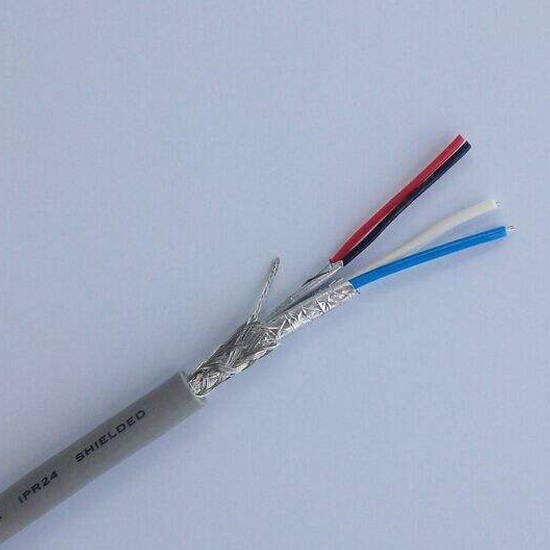
After the slave transmission is complete, the slave puts itself back into receive mode so that the master can transmit additional commands. In this manner, data can be exchanged between the master and each slave on the bus. Transmissions are always initiated by the master device, and consist of an exchange of bytes. In RS485 mode, the RS422 transmit and receive pairs are shorted together with a pair of onboard jumpers as explained in the UART Wildcard Hardware: RS485 Jumpers section below. The default serial routines used by the onboard kernel assume that full duplex communications are available, so you cannot use the RS485 protocol to program the controller. Note that the local and the remote must share a common ground, so a minimum of 3 wires are required for half duplex RS485 communications: a pair of transceive wires and a common ground. This allows RS-485 to implement linear bus topologies using only two wires.
Multiple receivers may be connected to such a network in a linear, multidrop bus. This includes speed control using Variable Frequency Drives (VFD) or inverters, as well as controlling simple PLC and HMI network systems. The dual communications channels also provide an easy way to link systems that communicate using different serial protocols. Given the availability of ready-made communications cables, it is not necessary to study or understand the following descriptions of cable connections. These detailed signal descriptions and cable diagrams are presented to provide complete information for those who have special communications requirements and for those who wish to make their own application-specific communications cables. Thus RS485 is the standard protocol of choice when multi-drop communications are required. As a rule of thumb, the speed in bit/s multiplied by the length in metres should not exceed 108. Thus a 50-meter cable should not signal faster than 2 Mbit/s. The RS485 protocol uses differential data signals for improved noise immunity; thus RS485 can communicate over greater distances than RS232. Because differential signals have inherently better signal-to-noise properties, reliable RS422 communications can be sent over much longer distances compared to RS232.
RS232 allows both communicating parties to transmit and receive data at the same time; this is referred to as full duplex communications. The RS422 driver and receiver use separate differential conductor pairs on the serial cables, enabling full duplex communications. Each RS422 driver transmits a differential pair of output signals at 0 and 5 volts. In fact, a single driver chip on the UART Wildcard is used to implement both RS422 and RS485 communications for a given serial channel. The RS422 receiver converts the differential signal to the 0 to 5 volt logic signal required by the UART circuitry. This section also defines the logic states 1 (off) and 0 (on), by the polarity between A and B terminals. The next section describes the registers that configure and control the QScreen Controller’s SPI. This chapter describes those drivers, rs485 cable and presents code that makes it easy to configure the SPI for different data transfer rates and formats. C program’s source code file. If you have not yet compiled the GETSTART program and you want to do the exercises here, open GETSTART.C in your TextPad editor, click on the Make Tool, and after the compilation is done, enter Mosaic Terminal by clicking on the terminal icon and use the "Send File" menu item to send GETSTART.DLF to the QScreen Controller.
댓글목록
등록된 댓글이 없습니다.
